# Step-by-Step Guide: Modeling a U-Shaped Bracket in Tinkercad

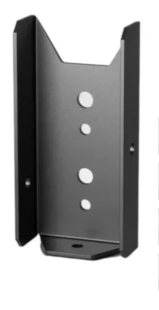
This guide provides a comprehensive, step-by-step walkthrough for designing the metal U-shaped bracket with mounting flanges (shown in your reference image) using basic shapes and boolean operations in Tinkercad.

---

## Overview & Dimensions Strategy
Before starting, keep in mind that Tinkercad uses millimeters (mm) by default.
* **Back Plate:** Acts as the anchor/spine.
* **Side Walls / Flanges:** Two vertical plates welded or bent upward.
* **Bottom Mounting Base:** A protruding flange with a beveled (chamfered) front edge and a central mounting hole.
* **Hole Patterns:** Multiple vertical holes on the back spine and single side-wall holes for fastening.

---

## Step 1: Building the Main U-Channel Body

1. **Place the Back Panel:**
   * Drag a standard **Box** onto the workplane.
   * Adjust dimensions using the white handles or inspector panel:
     * **Width ($X$):** e.g., `40 mm`
     * **Height ($Z$):** e.g., `80 mm`
     * **Thickness/Depth ($Y$):** `3 mm` (representing sheet metal thickness)

2. **Add the Side Walls:**
   * Drag two more **Boxes** onto the workplane.
   * Set their dimensions:
     * **Width ($X$):** `3 mm` (matching thickness)
     * **Depth ($Y$):** e.g., `50 mm`
     * **Height ($Z$):** `80 mm` (matching the back plate)
   * Position one box flush against the left edge of the back panel, and the second box flush against the right edge.

3. **Group the U-Channel:**
   * Select all three boxes together.
   * Press `Ctrl + G` (or click the **Group** icon) to combine them into a single U-shaped profile.

---

## Step 2: Creating the Bottom Mounting Base & Chamfers

1. **Base Plate Extrusion:**
   * Drag a flat **Box** to the bottom of the U-channel, positioned so it extends forward (outward from the front of the bracket).
   * Dimensions:
     * **Width ($X$):** Matches the total outer width of the bracket (`46 mm` if side walls are 3mm thick).
     * **Depth ($Y$):** e.g., `25 mm` extension forward.
     * **Thickness ($Z$):** `3 mm`.

2. **Chamfering the Corners:**
   * Notice the front corners of the bottom base are angled (beveled).
   * Drag two **Box (Hole)** shapes, rotate them to 45 degrees, and place them overlapping the front-left and front-right corners of the base plate.
   * Group the base plate with these two hole wedges to slice off the corners cleanly.

3. **Bottom Mounting Hole:**
   * Drag a **Cylinder (Hole)** onto the workplane.
   * Set dimensions (e.g., diameter of `6 mm` for a standard bolt).
   * Use the **Align Tool (`L`)** to center it precisely along the centerline of the bottom base plate.
   * Group the base plate and the cylinder hole.

---

## Step 3: Shaping the Top Edges and Notches

1. **Angled Top Cuts on Side Walls:**
   * The top of each side wall angles downward toward the back spine.
   * Place a **Roof** shape or a rotated **Box (Hole)** over the top corners of the side walls.
   * Adjust the angle/position to slice off the top-front corners diagonally.

2. **Center Notch on the Back Panel Top Edge:**
   * Drag a rectangular **Box (Hole)** and position it centered on the top edge of the back panel.
   * Group it with the main bracket to carve out the central square/trapezoidal notch.

---

## Step 4: Adding the Fastener Holes

1. **Back Panel Hole Pattern:**
   * Drag a series of **Cylinder (Holes)** onto the workplane.
   * In the reference image, there is a vertical sequence of alternating or graduated holes down the center spine.
   * Set up your cylinder heights/diameters accordingly.
   * Select all back holes and use the **Align Tool** to align them along the exact vertical center axis of the back plate.

2. **Side Wall Holes:**
   * Drag a **Cylinder (Hole)**, rotate it `90 degrees` on the $Y$ or $X$ axis so it points horizontally.
   * Position it on the left side wall, and duplicate it for the right side wall.

3. **Final Grouping:**
   * Select your entire model (the bracket structure plus all hole cylinders).
   * Press `Ctrl + G` to execute all cuts simultaneously.

---

## Pro-Tips for Tinkercad Success

* **Grid Snap:** Set your snap grid to `0.1 mm` or `0.5 mm` for precise fine-tuning.
* **The Align Tool (`L`):** Vital for making sure holes are perfectly centered without eyeballing.
* **Transparent View:** Press `T` on selected shapes to toggle transparency, making it much easier to see where your holes are positioned internally.